- A circuit which produces electrical oscillations of any desired frequency is known as oscillatory circuit or tank circuit.
- A circuit which produces sinusoidal oscillations of any desired frequency is known as sinusoidal oscillator.
- A simple oscillatory circuit consists of a capacitor (C) and inductance (L) in parallel as shown below
(1) In the position shown in figure (i), the upper plate of capacitor has deficit of electrons and the lower plate has excess of electrons. Therefore, there
is a voltage across the capacitor and the capacitor has electro-static energy.
(2) When switch S is closed as shown in figure (ii), the capacitor will discharge through inductance and the electron flow will be in the direction indicated by the arrow. This current flow sets up magnetic field around the coil. Due to the inductive effect, the current builds up slowly towards a maximum value. The circuit current will be maximum when the capacitor is fully discharged. At this instant, electro-static energy is zero but because electron motion is greatest, the magnetic field energy around the coil is maximum. Obviously, the electro-static energy across the capacitor is completely converted into magnetic field energy around the coil.
(3) Once the capacitor is discharged, the magnetic field will begin to collapse and produce a counter e.m.f. according to Lenz’s law, the counter e.m.f will keep the current flowing in the same direction. The result is that the capacitor is now charged with the opposite polarity, making upper plate of capacitor negative and lower plate positive as shown in figure (iii).
(4) After the collapsing field has recharged the capacitor, the capacitor now
begins to discharges, current now flowing in the opposite direction. Figure (iv) shows capacitor fully charged and maximum current flowing. The sequence of charge and discharge results in alternating motion of electrons or an oscillating current. The energy is alternately stored in the electric field of the capacitor (and the magnetic field of inductance coil (L) . This interchange of energy between L and C is repeated over. and again resulting in the production of oscillation.
- So the charge and discharge of condenser through inductance results in oscillating current and hence the electrical oscillations are set up in LC circuit whose frequency is given by, f = 1/ 2π√LC.
WAVEFORM:
- If there were no losses in the tank circuit to consume the energy, the interchange of energy between L and C would continue indefinitely.
- In a practical tank circuit, there are resistance and radiation losses in the coil and dielectric losses in the capacitor.
- During each cycle, a small part of the originally imparted. energy is used up to overcome these losses.
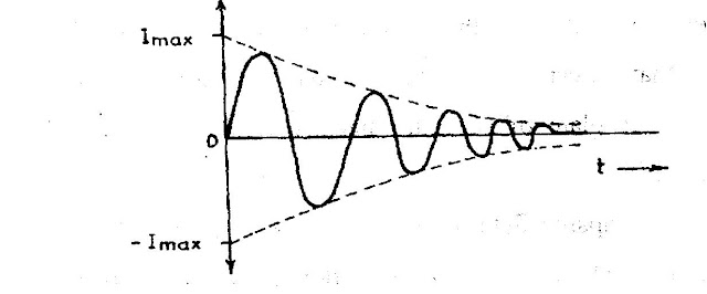
- The result is that the amplitude of oscillating current decreases gradually and eventually it becomes zero when all the energy is consumed as losses.
- Therefore, the tank circuit by itself will produce damped oscillations as shown below.
STABILIZATION OF AMPLITUDE:
- In all the oscillators the output waveform tends to be the maximum possible output that the amplifier can produce.
- Having large amplitudes will distort the output amplitude since the output amplitude is limited only by the amplifier output range.
- To minimize distortion and reduce the amplitude of the output waveform to an acceptable level amplitude stabilization circuitry must be employed.
- Amplitude stabilization operates by ensuring that oscillation ceases as the amplifier output approaches a predetermined level.
- As the output falls to an acceptable level the circuit continues to oscillate. For phase shift oscillators the amplifier gain should always exceed 29 to sustain oscillations.


Really helpful! ✨
ReplyDelete