Showing posts with label BASIC CONCEPTS OF FLUID MECHANICS. Show all posts

PINS AND SIGNALS OF 8031/8051 MICROCONTROLLER

•    The INTEL 805 F is an 8-bit microcontroller with 128 byte internal RAM and 4kb internal ROM.

•    The INTEL 8031 is same, as 8051 except that it does not have internal ROM.

•    The 8051 is a pin 40 pin IC available in Dual-In line package (DIP).

•    Requires a single power supply of +5V.

•    Its maximum internal clock frequency rating is 12 MHz.


Pin Diagram for 8051/8031 microcontroller


Signals of 8031/8051 microcontroller

Alternate functions of port pins

Ports: (pin 1 to 8, pin 10 to 17, pin 21 to 28 and pin 32 to 39)

•    The 8031/8051 microcontroller has 32 I/O pins and they are organized as four numbers of 8-bit parallel port.

•    The ports are denoted as port-0, port-1, port-2 and port-3. Each port can be used as either 8-bit parallel port or 8 numbers of 1-bit ports.

•    The ports behave as latches during output operation and behave as buffers during input operation.

•    Port-1 can be used only for I/O operation

•    When external memory is employed, the port-0 function as multiplexed low byte address or data lines, and port-2 function as high byte address lines. Therefore for accessing external memory the microcontroller uses 16-bit address and access the memory in bytes. Hence the addressable memory space is 64 kb (216 = 64kb).

•    The 8031/8051 allows the external memory to be organized as two banks of 64 kb. One is program/code memory and the other is data memory.

PSEN (low signal): pin 29

•    The signal PSEN (low) is used as read control/enable for program memory.

RD (low signal) and WR (low signal): pin 17 and pin 16

•    The port pin P3.7 function as read control and the port pin P3.6 function as write control for data memory.

•    When two external memory banks are not desirable, the PSEN (low) and RD (low) should be externally ANDed to provide a single read control signal. In such cases the controller will access a common memory space (of maximum capacity 64 kb) for program and data.

•    ALE is used to demultiplex the low byte address or data using an external latch.

EA (Low)/Vpp : pin 31

•    When the microcontroller access program from external memory, then this pin is low. ie. EA (low) is enabled.

•    When the microcontroller access program from internal memory, then this pin is high. At that time this pin is used to supply programming voltage +12V to EPROM/ROM.

XTAL 1 AND XTAL2: PIN 19 AND PIN18

•    The XTAL 1 and XTAL2 pins are provided for external quartz crystal connection, in order to generate the required clock for the microcontroller. The maximum frequency of quartz crystal that can be connected to 8031/8051 microcontroller is 12 MHz.

RST (low): pin 9


•    The RST(low) signal is used to reset the microcontroller in order to bring the controller to a known state.

Contents of register after reset

INTERRUPTS: pin 12 to 15

•    The 803 1/8051 has five interrupts.

•    In this two interrupts are external interrupt as INT0 (Low), INT1 (Low) and the remaining three are internal interrupts as timer-0, timer-1 and serial port.

•    All interrupts are maskable and vectored interrupts.

Vector address and priority of interrupts

ORIFICE METER


The  Venturi  meter  described  earlier  is  a  reliable  flow-measuring  device. Furthermore, it causes little pressure loss.

For these reasons it is  widely used, particularly for large-volume liquid  and gas flows. However this meter is relatively complex to construct and hence expensive.  Especially  for  small  pipelines,  its  cost  seems  prohibitive,  so simpler devices such as orifice meters are used.

The orifice meter consists of a flat orifice plate with a circular hole drilled in it. There  is  a  pressure  tap  upstream  from  the  orifice  plate  and  another  just downstream.

The principle of the orifice meter is identical with that of the venturi meter.


The reduction of the cross section of the flowing stream in passing through the orifice increases the velocity head at the expense of the pressure head, and manometer measures the reduction in pressure between the taps.

Bernoulli's equation  provides a  basis for correlating the increase  in velocity head with the decrease in pressure head.

VENTURIMETER


In  this  meter  the  fluid  is  accelerated  by  its  passage  through  a  converging cone of angle 15-20o.

The pressure difference between the upstream end if the cone and the throat are measured and provide the signal for the rate of flow.

The fluid  is  then  retarded in  a  cone of  smaller  angle  (5-7o) in  which  large proportion of kinetic energy is converted back to pressure energy.

Because of the gradual reduction in the area there is no vena contracta and the flow area is a minimum at the throat so that the coefficient of contraction
is unity.


The attraction of this meter lies in its high-energy recovery so that it may be used where only a small pressure head is available, though its construction
is expensive.

To  make  the  pressure  recovery  large,  the  angle  of  downstream  cone  is small, so boundary layer separation is prevented and friction minimized.

Since separation does not occur in a contracting cross section, the upstream cone can be made shorter than the downstream cone  with but little friction, and space and  material are thereby conserved.

Although Venturimeter can be applied to the measurement of gas, they are most commonly used for liquids.

The following treatment is limited to incompressible fluids.

The basic equation for the venturimeter is obtained by writing the Bernoulli equation for incompressible fluids between the two sections a and b. Friction is neglected, the
meter is assumed to be horizontal.

BERNOULLI’S PRINCIPLE l EQUATION


Bernoulli equation is arrived from the following assumptions:

1. Steady flow - common assumptions applicable to many flows.

2. Incompressible flow - acceptable if the flow Mach number is less than 0.3.

3. Frictionless flow - very restrictive; solid walls introduce friction effects.

4. No shaft work - no pump or turbines on the streamline.

5. No transfer of heat - either added or removed.


Range of validity of the Bernoulli Equation:

Bernoulli   equation   is   valid   along   any   streamline   in   any   steady,   inviscid, incompressible
flow. There are no restrictions on the shape of the streamline or on the geometry of
the overall flow. The equation is valid for flow in one, two or three dimensions.


Modifications on Bernoulli equation:


Bernoulli equation can be corrected and used in the following form for real cases.


Derivation of Bernoulli equation from Euler's Equation of Motion:

Mass in per unit time = ȡ Av = m
For steady flow, mass out per unit time = m
Rate of momentum in = m v
Rate of momentum out = m (v + dv)
Rate of increase of momentum from AB to CD = m (v + dv) - m v = ȡ Avdv
Force due to p in the direction of motion = pA
Force due to p + dp opposing the direction of motion = (p + dp)(A + dA)
Force due to pside producing a component in the direction of motion = p side dA
Force   due   to  mg   producing   a   component   opposing   the   direction  of   motion=
mgcos(ș)
Resultant force in the direction of motion
= pA - (p + dp)(A + dA) + p side dA - mgcos(ș)
The value of pside will vary from p at AB to p + dp at CD, and can be taken as p +
kdp
where k is fraction.
Mass of fluid element ABCD = m =  ȡ g(A + 1/2 dA) ds
And ds = dz/cos(ș); since cos(d z/ds) Substituting in equn.2,
Resultant force in the direction of motion
pA - (p + dp)(A + dA) + p + kdp - ȡ g(A + 1/2 dA) dz
= -Adp - dpdA + k ȡ pdA - ȡ gAdz - 1/2 dAdz
Neglecting products of small quantities,
Resultant force in the direction of motion = -Adp - ȡ gAdz Applying Newton's second law, (i.e., equating equns.1 & 3) dAv dv = -Adp - ȡ gAdz
Dividing by dAds,


Fluid Flow Characteristics


Flow   characteristics    deals    with   the   methods    of    determining   velocity   and acceleration. The fluid flow is classified as given below:

a) Steady and Unsteady Flows:

•    Steady flow is defined as  that  type  of  flow in  which the  fluid characteristics like velocity, pressure, density, etc. at a point do not change with time.

•    Unsteady flow is that type of flow, in which the velocity, pressure of density
at a point changes with respect to time.

b) Uniform and Non-uniform Flows:

•    Uniform flow is defined as that type of flow in which the velocity at any given time  does not change  with  respect  to space  (i.e., length  of  direction  of  the flow).

•    Non-uniform flow is that type of flow in  which the velocity at any given time changes with respect to space.

c) Laminar and Turbulent Flows:

•    Laminar flow is defined as that type of flow in which the fluid particles move along well-defined paths or stream lines and all the stream-lines are straight and parallel. Thus the particles move in laminas or layers gliding smoothly over the adjacent layer.  This type of flow is also called stream-line flow or viscous flow.

•    Turbulent flow is that type of flow in which the fluid particles move in zig-zag way. Due to the movement of fluid particles in a zig-zag way, the eddies formation takes place which the responsible for high energy loss. For a pipe flow, the type of flow is determined by a non-dimensional number VD/v called the Reynolds number, where D = Diameter of pipe; V = Mean velocity of flow in pipe; and v = Kinematic viscosity of fluid.

•    If the  Reynolds  number  is less  than  2000,  the flow is called  laminar.  If  the Reynolds  number  is  more  than  4000,  it  is  called  turbulent  flow.  If  the Reynolds  number  lies  between  2000  an  4000,  the  flow may  be laminar  or turbulent.

d) Compressible and Incompressible Flows:

•    Compressible flow is that type of flow in which the density of the fluid change from point to  point or in  other  words  the  density  (ȡ) is  not constant for  the fluid flow.

•    Incompressible flow is that type of flow in which the density of the fluid does not change from point to point or in other words  the density (ȡ) is constant for the fluid flow.

e) Rotational and Irrotational Flows:

•    Rotational  flow is that  type  of flow in  which  the fluid  particles  while flowing along stream-lines also rotate about their own axis.

•    If the fluid particles while flowing along stream-lines, do not rotate about their own axis, that type of flow is called irrotational flow.

f) One, Two and Three Dimensional Flows:


One-dimensional flow is that type of flow in which the flow parameter such as
velocity is  a  function  of  time  and  one  space  co-ordinate only, say x. For a steady one dimensional flow, the velocity is a function of one-space-co-ordinate only. The variation  of  velocities  in  other  two  mutually  perpendicular  directions  is  assumed negligible.

Two-dimensional flow is that type of flow in which the velocity is a function of
time  and  two  rectangular  space  co-ordinates  say  x  and  y.  For  a  steady  two- dimensional  flow  the  velocity  is  a  function  of  two  space  co-ordinates  only.  The variation of velocity in the third direction is negligible.

Three-dimensional flow is that type of flow in which the velocity is a function of
time and three mutually perpendicular directions. But for a steady three-dimensional flow the fluid parameters are functions of three space co-ordinates (x y and z) only.

Rate of Flow or Discharge (Q):
It is defined as the quantity of a fluid flowing per second through a section of a pipe
or a channel. For an incompressible fluid (or liquid) the rate of flow or discharge is expressed  as  the  volume  of  fluid  flowing  across  the  section  per  second.  For compressible  fluids,  the  rate  of  flow  is  usually  expressed  as  the  weight  of  fluid following across the section. Thus For liquids the units of Q are m3/sec of litres/sec
For gases and units of Q is kgf/sec or Newton/sec Consider a liquid flowing through
a pipe in which A=Cross-sectional area of pipe. V=Average velocity of fluid across the section.
Then discharge Q = A x V


Continuity Equation:

Let us make the mass balance for a fluid element as shown below-an open-faced cube):


Mass balance:

Accumulation  rate  of  mass  in  the  system  =  all  mass  flow rates  in  -  all  mass  flow rates out    --------------------- (1)
The  mass  in  the  system  at  any  instant  is  ȡ    x    y    z.  The  flow  into  the  system
through face 1 is
m1  =   ȡ1 vx1     y   z.
And the flow out of the system through face 2 is m2  =   ȡ2 vx2     y   z.
Similarly for the faces 3, 4, 5, and 6 are written as follows:

m3  =    ȡ3 vx3    x    z.
m4  =    ȡ4 vx4    x    z.

Substituting these quantities in equn.1, we get


Manometers


A somewhat more complicated device for measuring fluid pressure consists of a bent tube containing one or more liquid of different specific gravities. Such a device is known as manometer.

In using a manometer, generally a known pressure (which may be atmospheric) is applied to one end of the manometer tube and the unknown pressure to be determined is applied to the other end.

In some cases, however, the difference between pressure at ends of the manometer tube is desired rather than the actual pressure at the either end. A manometer to determine this differential pressure is known as differential pressure manometer.


The maximum value of P1 - P2 is limited by the height of the manometer. To measure larger pressure differences we can choose a manometer with higher density, and to measure smaller pressure differences with accuracy we can choose a manometer fluid which is having a density closer to the fluid density.


Inverted U - tube Manometer


Two fluid U-tube Manometer

Small differences in pressure in gases are often measured with
a manometer of the form shown in the figure.


The manometer in its various forms is an extremely useful type of pressure measuring instrument, but suffers from a number of limitations.

While it can be adapted to measure very small pressure differences, it can not be used conveniently for large pressure differences - although it is possible to connect a number of manometers in series and to use mercury as the manometric fluid to improve the range. (limitation)

A manometer does not have to be calibrated against any standard; the pressure difference can be calculated from first principles. ( Advantage)

Some liquids are unsuitable for use because they do not form well-defined menisci. Surface tension can also cause errors due to capillary rise; this can be avoided if the diameters of the tubes are sufficiently large - preferably not less than 15 mm diameter. (limitation)

A major disadvantage of the manometer is its slow response, which makes it unsuitable for measuring fluctuating pressures.(limitation)

It is essential that the pipes connecting the manometer to the pipe or vessel containing the liquid under pressure should be filled with this liquid and there should be no air bubbles in the liquid.(important point to be kept in mind)

PASCAL’S LAW

It states that the pressure or intensity of pressure at a point in a static fluid is equal in all directions.

Capillarity:


Rise or fall of a liquid in a capillary  tube is caused by surface tension and depends on the relative magnitude of cohesion of the liquid and the adhesion of the liquid to the walls of the containing vessel. Liquids rise in tubes if they wet (adhesion > cohesion) and fall in tubes that do not wet (cohesion > adhesion).


Wetting and contact angle

Fluids wet some solids and do not others.

The figure shows some of the possible wetting behaviors of a drop of liquid
placed on a horizontal, solid surface (the remainder of the surface is covered with air, so two fluids are present).
Figure.(a) represents the case of a liquid which wets a solid surface well, e.g.
water on a very clean copper. The angle    shown is the angle between the edge
of the liquid surface and the solid surface, measured inside the liquid. This angle
is called the contact angle and is a measure of the quality of wetting.
For perfectly wetting, in which the liquid spreads, as a thin film over the surface
of the solid, Ĭ is zero.


Fig.(c) represents the case of no wetting. If there were exactly zero wetting, Ĭ
would be 180o. However, the gravity force on the drop flattens the drop, so that
180o angle is never observed. This might represent water on teflon or mercury on clean glass. We normally say that a liquid wet a surface if Ĭ is less than 90o and does not wet if Ĭ is more than 90o. Values of Ĭ  less than 20o are considered
strong wetting and values of Ĭ greater than 140o are strong non wetting.

Capillarity
is important (in fluid measurements) when using tubes smaller than about 10 mm in diameter Capillary rise (or depression) in a tube can be

calculated by making force balances. The forces acting are forces due to surface
tension and gravity. The
force due to surface tension, Fs = Ʌd ı cos( Ĭ), where Ĭ is the wetting angle or contact angle. If tube (made of glass) is clean Ĭ is zero for water and about 140o
for Mercury. This is opposed by the gravity force on the column of fluid, which is
equal to the height of the liquid which is above (or below) the free surface and which equals Fg = (Ʌ/4)d2hg ȡ, where ȡ  is the density of liquid. Equating these forces and  solving for Capillary rise (or depression), we find
h = 4ıcos( Ĭ)/( ȡ gd).

Surface Tension


A molecule I in the interior of a liquid is under attractive forces in all directions and the vector sum of these forces is zero.

But a molecule S at the surface of a liquid is acted by a net inward cohesive force that is perpendicular to the surface.

Hence it requires work to move molecules to the surface against this opposing force, and surface molecules have more energy than interior ones.

The surface tension (    sigma) of a liquid is the work that must be done to bring enough molecules from inside the liquid to the surface to form one new unit area of that surface.

It is also defined as “ the tensile force acting on the surface of a liquid in contact with a gasor on the surface between two immiscible liquids such that the contact surface behaves like a membrane under tension. It is denoted by

(J/m2 = N/m). (1 dyne/cm = 0.001 N/m).


Surface tension is the tendency of the surface of a liquid to behave like a stretched elastic membrane.


Surface Tension on Liquid Droplet


There is a natural tendency for liquids to minimize their surface area. For this reason, drops of liquid tend to take a spherical shape in order to minimize surface area.


For such a small droplet, surface tension will cause an increase of internal pressure p in order to balance the surface force.

We will find the amount  (dp = p - poutside) by which the pressure inside a liquid droplet of radius r, exceeds the pressure of the surrounding vapor/air by making force balances on a hemispherical drop. Observe that the internal pressure p is trying to blow apart the two hemispheres, whereas the surface tension    is trying
to pull them together. Therefore, dp Ʌr2 = 2Ʌr    ı

i.e. dp = 2ı/r (for liquid droplet)

Similar force balances can be made for cylindrical liquid jet.

dp 2r= 2ı

i.e. dp = ı/r (for cylindrical liquid jet)

Similar treatment can be made for a soap bubble that is having two free
surfaces.

dp Ʌr2  = 2X2Ʌr  ı   i..e  p = 4ı/r (for a soap bubble)

Surface tension generally appears only in situations involving either free surfaces
(liquid/gas or liquid/solid boundaries) or interfaces (liquid/liquid boundaries); in the latter case, it is usually called the interfacial tension.


Universal Gas Constant:


Real gases below critical pressure and above the critical temperature
obey perfect gas law which is a combination of Boyle’ s and Charle’ s law.

Boyle’ s law states that for constant temperature, the density varies directly as absolute pressure.

Charle’ s law states that for constant pressure, the volume of a given mass
of gas varies as its absolute pressure.

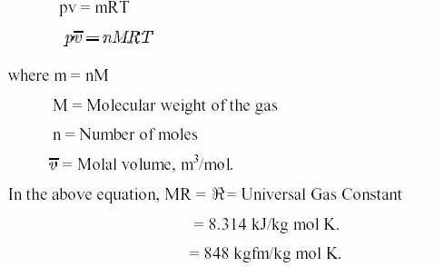
Thus, pv = mRT

On molal basis, the above equation is expressed as


1. Isothermal process: An isothermal process in the one in which temperature
remains constant.

i.e. pv = Constant.

2. Adiabatic Process: An adiabatic process in the one in which there is no heat transfer
to and from the gas. i.e. pvr = Constant,


where r is the ratio of specific heat of gas at constant pressure and constant volume.= Cp/Cv, 1.4 for air.

CONSTRUCTION OF D.C. MACHINE


  • •    A dc machine can either be operated as a generator or as a motor.
  • •    Therefore the construction is same for both dc generator and dc motor.
  • •    The sectional view of the dc machine is shown in the following Figure.

The main parts in a dc machine are

1. Yoke or magnetic frame

2. Magnetic poles

3. Field coils

4. Inter poles (or) Commutator poles

5. Armature and Armature coils

6. Commutator and Brushes

7. Bearings and End covers


Yoke or magnetic frame
  • •    It is made of cast iron for small machines. For large machines, it is made of cast steel.

Function of yoke

i)    It provides mechanical support for the machine and acts as a cover
for the machine

ii)    It forms the portion of a magnetic circuit.

Magnetic poles
  • •    The field magnet consists of pole cores and pole shoes.
  • •    The pole cores and pole shoes are built with thin laminations of annealed steel and are held together using rivets or under hydraulic pressure.
  • •    These magnetic poles are fitted to the yoke using screws.
  • •    An advantage of pole cores built up of laminations is that eddy current losses in the pole faces are minimized.

Function of pole shoes

(i)    They spread out the flux in the air gap and also reduce the reluctance of the magnetic path at its larger cross section.

(ii)    They support the exciting coils or field coils.

      Field coils


  • •    Field coils are wound with enameled copper wire. Sometimes cotton insulation is used.
  • •    The coils are dried in vaccum and then impregnated with an insulating compound.
  • •    Sufficient space is left between the layers for ventilating purposes.
  • •    The exciting coils on the inter poles are connected in series with the armature.
  • •    So they carry the full armature current and are made up of a few turns of heavy conductor.
Interpoles or Commutating poles

Inter poles are present in the high capacity dc machines.

Function of Interpoles or Commutating poles

 (i) To improve commutation and

(ii) To reduce armature reaction

Armature and Armature coils

•    When the armature is revolving, it is subjected to alternating magnetization.
•    This causes hysteresis loss.
•    To minimize this loss, low hysteresis steel containing a few percentage of silicon is used in the armature.
•    To reduce the eddy current loss, laminations are provided .

•    The armature coils are wound with single cotton covered or double cotton covered or enameled insulated wires.
•    These coils are put into the insulated slots of the armature to avoid short circuit between the armature conductors and core.
•    The slots are closed by fiber or wooden wedges to prevent the conductors from plying out due to the centrifugal force caused by the rotation of the armature.
•    The armature is impregnated with varnish and dried. In medium and small machines, circular conductors are used.
•    In large machines, rectangular strips of conductors are used for winding the armature coils.

Commutator

•    It is made of wedge shaped segments of hard drawn (or) drop forged copper insulated from each other by thin layers of built-up mica.
•    The segments are held together by clamping them using Vshaped end rings and insulated from the segments by V shaped micanite rings.
•    Each segment is provided with a riser to which the leads of the armature coils are soldered.


Brushes

•    The purpose of brush is to carry the current from the commutator to the external circuit.
•    It is made of carbon or copper. For low voltage machines, it is made of copper-carbon compound.
•    The brushes are placed in the brush holder, which is kept pressed against the commutator by a spring.
•    The brush holder is fitted to a spindle, which is insulated from the machine.
•    Connections from the brushes are taken by means of flexible pigtails, made of copper ribbons.


Bearings and End covers

•    End covers are made of cast iron or fabricated steel are fitted to both ends of the yoke.
•    To these end covers either ball bearings or roller bearings are fitted and armature shaft is mounted over these bearings.
•    These bearings are lubricated with grease or hard oi


Armature winding fundamentals

•    In modern dc machines, drum type of armature windings is provided. In this type, the coils are wound and placed into the insulated slots of the armature.
•    A coil with more than one turn is known as multi turn coil.
•    The coils are always placed in two slots which are approximately one pole pitch apart.
•    The portion of a coil placed inside a slot is called coil side and each coil will have number of conductors.
•    The distance between the two coil sides of a coil is termed as coil pitch, which is expressed in terms of
number of slots.
•    The ends of a coil are connected to two different commutator segments on the commutator.
•    The distance in terms of number of commutator segments, between the commutator segments to which the ends of a coil are connected is called commutator pitch.
•    The double layer windings are present in the dc machine. In double layer winding there will be two coil sides belonging to two different coils in each slot.
•    If a coil side of one coil is laid in the top layer of a slot, the other coil side of the same coil occupies the bottom layer of the slot usually one pole pitch.

Drum type of winding has two types.

1. Lap winding

2. Wave winding

Lap winding

•    In lap winding each coil is connected in series with next coil under the same pole pair.
•    If the start of one coil is connected to one particular commutator segment, the end of that coil and start of the next coil are connected to the next commutator segment either to the right or left of the first commutator segment.
•    This process is continued till all the coils are connected. Here the commutator pitch is always + 1.
•    In lap winding there are as many parallel paths as there are number of poles.
•    The emf induced in any generator is equal to the emf induced in all the coils in a parallel path.
•    Therefore lap winding is used in low voltage large current dc machines.


Labels

PROJECTS 8086 PIN CONFIGURATION 80X86 PROCESSORS TRANSDUCERS 8086 – ARCHITECTURE Hall-Effect Transducers INTEL 8085 OPTICAL MATERIALS BIPOLAR TRANSISTORS INTEL 8255 Optoelectronic Devices Thermistors thevenin's theorem MAXIMUM MODE CONFIGURATION OF 8086 SYSTEM ASSEMBLY LANGUAGE PROGRAMME OF 80X86 PROCESSORS POWER PLANT ENGINEERING PRIME MOVERS 8279 with 8085 MINIMUM MODE CONFIGURATION OF 8086 SYSTEM MISCELLANEOUS DEVICES MODERN ENGINEERING MATERIALS 8085 Processor- Q and A-1 BASIC CONCEPTS OF FLUID MECHANICS OSCILLATORS 8085 Processor- Q and A-2 Features of 8086 PUMPS AND TURBINES 8031/8051 MICROCONTROLLER Chemfet Transducers DIODES FIRST LAW OF THERMODYNAMICS METHOD OF STATEMENTS 8279 with 8086 HIGH VOLTAGE ENGINEERING OVERVOLATGES AND INSULATION COORDINATION Thermocouples 8251A to 8086 ARCHITECTURE OF 8031/8051 Angle-Beam Transducers DATA TRANSFER INSTRUCTIONS IN 8051/8031 INSTRUCTION SET FOR 8051/8031 INTEL 8279 KEYBOARD AND DISPLAY INTERFACES USING 8279 LOGICAL INSTRUCTIONS FOR 8051/8031 Photonic Transducers TECHNOLOGICAL TIPS THREE POINT STARTER 8257 with 8085 ARITHMETIC INSTRUCTIONS IN 8051/8031 LIGHTNING PHENOMENA Photoelectric Detectors Physical Strain Gage Transducers 8259 PROCESSOR APPLICATIONS OF HALL EFFECT BRANCHING INSTRUCTIONS FOR 8051/8031 CPU OF 8031/8051 Capacitive Transducers DECODER Electromagnetic Transducer Hall voltage INTEL 8051 MICROCONTROLLER INTEL 8251A Insulation Resistance Test PINS AND SIGNALS OF 8031/8051 Physical Transducers Resistive Transducer STARTERS Thermocouple Vacuum Gages USART-INTEL 8251A APPLICATIONs OF 8085 MICROPROCESSOR CAPACITANCE Data Transfer Instructions In 8086 Processors EARTH FAULT RELAY ELECTRIC MOTORS ELECTRICAL AND ELECTRONIC INSTRUMENTS ELECTRICAL BREAKDOWN IN GASES FIELD EFFECT TRANSISTOR (FET) INTEL 8257 IONIZATION AND DECAY PROCESSES Inductive Transducers Microprocessor and Microcontroller OVER CURRENT RELAY OVER CURRENT RELAY TESTING METHODS PhotoConductive Detectors PhotoVoltaic Detectors Registers Of 8051/8031 Microcontroller Testing Methods ADC INTERFACE AMPLIFIERS APPLICATIONS OF 8259 EARTH ELECTRODE RESISTANCE MEASUREMENT TESTING METHODS EARTH FAULT RELAY TESTING METHODS Electricity Ferrodynamic Wattmeter Fiber-Optic Transducers IC TESTER IC TESTER part-2 INTERRUPTS Intravascular imaging transducer LIGHTNING ARRESTERS MEASUREMENT SYSTEM Mechanical imaging transducers Mesh Current-2 Millman's Theorem NEGATIVE FEEDBACK Norton's Polarity Test Potentiometric transducers Ratio Test SERIAL DATA COMMUNICATION SFR OF 8051/8031 SOLIDS AND LIQUIDS Speed Control System 8085 Stepper Motor Control System Winding Resistance Test 20 MVA 6-digits 6-digits 7-segment LEDs 7-segment A-to-D A/D ADC ADVANTAGES OF CORONA ALTERNATOR BY POTIER & ASA METHOD ANALOG TO DIGITAL CONVERTER AUXILIARY TRANSFORMER AUXILIARY TRANSFORMER TESTING AUXILIARY TRANSFORMER TESTING METHODS Analog Devices A–D BERNOULLI’S PRINCIPLE BUS BAR BUS BAR TESTING Basic measuring circuits Bernoulli's Equation Bit Manipulation Instruction Buchholz relay test CORONA POWER LOSS CURRENT TRANSFORMER CURRENT TRANSFORMER TESTING Contact resistance test Current to voltage converter DAC INTERFACE DESCRIBE MULTIPLY-EXCITED Digital Storage Oscilloscope Display Driver Circuit E PROMER ELPLUS NT-111 EPROM AND STATIC RAM EXCITED MAGNETIC FIELD Electrical Machines II- Exp NO.1 Energy Meters FACTORS AFFECTING CORONA FLIP FLOPS Fluid Dynamics and Bernoulli's Equation Fluorescence Chemical Transducers Foil Strain Gages HALL EFFECT HIGH VOLTAGE ENGG HV test HYSTERESIS MOTOR Hall co-efficient Hall voltage and Hall Co-efficient High Voltage Insulator Coating Hot-wire anemometer How to Read a Capacitor? IC TESTER part-1 INSTRUMENT TRANSFORMERS Importance of Hall Effect Insulation resistance check Insulator Coating Knee point Test LEDs LEDs Display Driver LEDs Display Driver Circuit LM35 LOGIC CONTROLLER LPT LPT PORT LPT PORT EXPANDER LPT PORT LPT PORT EXTENDER Life Gone? MAGNETIC FIELD MAGNETIC FIELD SYSTEMS METHOD OF STATEMENT FOR TRANSFORMER STABILITY TEST METHODS OF REDUCING CORONA EFFECT MULTIPLY-EXCITED MULTIPLY-EXCITED MAGNETIC FIELD SYSTEMS Mesh Current Mesh Current-1 Moving Iron Instruments Multiplexing Network Theorems Node Voltage Method On-No Load And On Load Condition PLC PORT EXTENDER POTIER & ASA METHOD POWER TRANSFORMER POWER TRANSFORMER TESTING POWER TRANSFORMER TESTING METHODS PROGRAMMABLE LOGIC PROGRAMMABLE LOGIC CONTROLLER Parallel Port EXPANDER Paschen's law Piezoelectric Wave-Propagation Transducers Potential Transformer RADIO INTERFERENCE RECTIFIERS REGULATION OF ALTERNATOR REGULATION OF THREE PHASE ALTERNATOR Read a Capacitor SINGLY-EXCITED SOLIDS AND LIQUIDS Classical gas laws Secondary effects Semiconductor strain gages Speaker Driver Strain Gages Streamer theory Superposition Superposition theorem Swinburne’s Test TMOD TRANSFORMER TESTING METHODS Tape Recorder Three-Phase Wattmeter Transformer Tap Changer Transformer Testing Vector group test Virus Activity Voltage Insulator Coating Voltage To Frequency Converter Voltage to current converter What is analog-to-digital conversion Windows work for Nokia capacitor labels excitation current test magnetic balance voltage to frequency converter wiki electronic frequency converter testing voltage with a multimeter 50 hz voltages voltmeter

Search More Posts

Followers