COMMON BASE CONFIGURATION OF A TRANSISTOR


COMMON BASE CONNECTION

In this configuration the input is applied between the emitter and base and the output is taken from the collector and the base. Here the base is common to both the input and the output circuits as shown in Fig.


In a common base configuration, the input current is the emitter current. and the output current is the collector current I The ratio of change in collector


current to the change in emitter current at constant collector-base voltage is called current amplification factor,


In a transistor VEB, IE, VCB, and IC are parameters.


  • These parameters can be interrelated in a number of ways. In these parameters the input current and the output voltage are taken as independent variables.


  • The input voltage and output current are then expressed in terms of these independent variables. And these dependent variables also be expressed in functional relationship.

                                                              i.e., VBE= f1 (IE,VCB)

                                                              IC= f2(In, VCB)


  • Thus the characteristics of a transistor is completely desired by the above two equations. These relationships can be conveniently displaced graphically.


  • The curves thus obtained are known as the static characteristics. The most important static characteristics are the input and the output characteristics

COMMON BASE CIRCUIT


  • A test circuit for determining the static characteristic of an NPN transistor is shown in Fig In this circuit, base is common to both the input and the output circuits.


  • To measure the emitter and the collector currents mull ammeters are connected in series with the emitter and the collector circuits.


  • Voltmeters are connected across the input and the output circuits to measure VBE and VCB There are two potentiometers R1 and R2 to vary the supply voltages VCC and VBE.


  • It is a curve, which shows the relationship between the emitter current, I and emitter-base voltage V at constant collector-base voltage V This method of determining the characteristic is as follows.


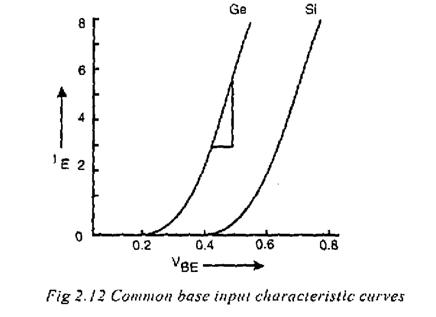
  • First by means of R1, a suitable voltage is applied to VCB from VCC. Next, voltages VBE is increased in a number of steps and corresponding values of IE are noted.


  • The emitter current is taken on the Y-axis and the emitter base voltage is taken on the X-axis. Fig 2.12 shows the input characteristic for germanium and silicon transistors.


The following points may be noted from the characteristics curves.

1.This characteristic may be used to find the input resistance of a transistor.The input resistance (ri) value is    given by the reciprocal of the input characteristic curve.

2.The emitter current IE increases rapidly with small increase in emitter- base voltage. It means that the input resistance is very high.

3.The emitter current is dependent of collector voltage.

OUTPUT CHARACTERISTICS


  • It is a curve which shows the relationship between the collector current IC and the collector-base voltage VCB at constant emitter current IE. This method of determining the characteristic is as follows.


  • First, by means of R2 a suitable voltage is applied to the base and the emitter. Next, VCB is increased from zero in a number of steps and corresponding values of IC are noted.


  • The above whole procedure is repeated for different values of IE for obtaining family of curves.


  • The collector-base voltage is taken the X-axis. Fig shows the family of output characteristics at different emitter current values.


  • The following points may be noted from the family of characteristic curves.


  • The collector current IC varies with VCB only at very low voltages.


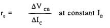
  • This characteristic may be used to find the output resistance (rO)


  • A very large change in collector-base voltage produces small change in collector current. It means that the output resistance is very high.


  • The collector current is constant above certain values of collector-base voltage. It means that IC is independent of VCB and depends upon IE only.

The output characteristics may be divided into three regions

1. The active region

2. Cut-off region

3. Saturation region

Active region: In this region the collector junction is reverse biased and the emitter junction is forward biased. In this region when IE= 0, IC = ICO. This reverse saturation current remains constant and is independent of collector voltage V as long as is below the break down potential. When emitter current flows in the emitter circuit then a fraction (- IE) of this current reaches the collector. Hence IC = - IE + ICO. Thus in the active region the collector current is independent of collector voltage and depends only upon the emitter current. But due to Early effect there is a small increase (0.5%) in IC with increase in VCB

Saturation region: The region to the left of the ordinate VCB = 0 is called the saturation region. In this region both junctions are forward biased. This is also called as bottomed region because the voltage has a fallen near the bottom of the characteristic where VCB = 0. In this region IC increases rapidly with even small increase VCB in as shown in Fig

Cut-off region: The region below the IE= 0 characteristic, for which the emitter and collector junction are both reverse biased, is called cut-off region. This portion of characteristic is not coincident with the voltage axis as shown in Fig.


No comments:

Post a Comment

Labels

PROJECTS 8086 PIN CONFIGURATION 80X86 PROCESSORS TRANSDUCERS 8086 – ARCHITECTURE Hall-Effect Transducers INTEL 8085 OPTICAL MATERIALS BIPOLAR TRANSISTORS INTEL 8255 Optoelectronic Devices Thermistors thevenin's theorem MAXIMUM MODE CONFIGURATION OF 8086 SYSTEM ASSEMBLY LANGUAGE PROGRAMME OF 80X86 PROCESSORS POWER PLANT ENGINEERING PRIME MOVERS 8279 with 8085 MINIMUM MODE CONFIGURATION OF 8086 SYSTEM MISCELLANEOUS DEVICES MODERN ENGINEERING MATERIALS 8085 Processor- Q and A-1 BASIC CONCEPTS OF FLUID MECHANICS OSCILLATORS 8085 Processor- Q and A-2 Features of 8086 PUMPS AND TURBINES 8031/8051 MICROCONTROLLER Chemfet Transducers DIODES FIRST LAW OF THERMODYNAMICS METHOD OF STATEMENTS 8279 with 8086 HIGH VOLTAGE ENGINEERING OVERVOLATGES AND INSULATION COORDINATION Thermocouples 8251A to 8086 ARCHITECTURE OF 8031/8051 Angle-Beam Transducers DATA TRANSFER INSTRUCTIONS IN 8051/8031 INSTRUCTION SET FOR 8051/8031 INTEL 8279 KEYBOARD AND DISPLAY INTERFACES USING 8279 LOGICAL INSTRUCTIONS FOR 8051/8031 Photonic Transducers TECHNOLOGICAL TIPS THREE POINT STARTER 8257 with 8085 ARITHMETIC INSTRUCTIONS IN 8051/8031 LIGHTNING PHENOMENA Photoelectric Detectors Physical Strain Gage Transducers 8259 PROCESSOR APPLICATIONS OF HALL EFFECT BRANCHING INSTRUCTIONS FOR 8051/8031 CPU OF 8031/8051 Capacitive Transducers DECODER Electromagnetic Transducer Hall voltage INTEL 8051 MICROCONTROLLER INTEL 8251A Insulation Resistance Test PINS AND SIGNALS OF 8031/8051 Physical Transducers Resistive Transducer STARTERS Thermocouple Vacuum Gages USART-INTEL 8251A APPLICATIONs OF 8085 MICROPROCESSOR CAPACITANCE Data Transfer Instructions In 8086 Processors EARTH FAULT RELAY ELECTRIC MOTORS ELECTRICAL AND ELECTRONIC INSTRUMENTS ELECTRICAL BREAKDOWN IN GASES FIELD EFFECT TRANSISTOR (FET) INTEL 8257 IONIZATION AND DECAY PROCESSES Inductive Transducers Microprocessor and Microcontroller OVER CURRENT RELAY OVER CURRENT RELAY TESTING METHODS PhotoConductive Detectors PhotoVoltaic Detectors Registers Of 8051/8031 Microcontroller Testing Methods ADC INTERFACE AMPLIFIERS APPLICATIONS OF 8259 EARTH ELECTRODE RESISTANCE MEASUREMENT TESTING METHODS EARTH FAULT RELAY TESTING METHODS Electricity Ferrodynamic Wattmeter Fiber-Optic Transducers IC TESTER IC TESTER part-2 INTERRUPTS Intravascular imaging transducer LIGHTNING ARRESTERS MEASUREMENT SYSTEM Mechanical imaging transducers Mesh Current-2 Millman's Theorem NEGATIVE FEEDBACK Norton's Polarity Test Potentiometric transducers Ratio Test SERIAL DATA COMMUNICATION SFR OF 8051/8031 SOLIDS AND LIQUIDS Speed Control System 8085 Stepper Motor Control System Winding Resistance Test 20 MVA 6-digits 6-digits 7-segment LEDs 7-segment A-to-D A/D ADC ADVANTAGES OF CORONA ALTERNATOR BY POTIER & ASA METHOD ANALOG TO DIGITAL CONVERTER AUXILIARY TRANSFORMER AUXILIARY TRANSFORMER TESTING AUXILIARY TRANSFORMER TESTING METHODS Analog Devices A–D BERNOULLI’S PRINCIPLE BUS BAR BUS BAR TESTING Basic measuring circuits Bernoulli's Equation Bit Manipulation Instruction Buchholz relay test CORONA POWER LOSS CURRENT TRANSFORMER CURRENT TRANSFORMER TESTING Contact resistance test Current to voltage converter DAC INTERFACE DESCRIBE MULTIPLY-EXCITED Digital Storage Oscilloscope Display Driver Circuit E PROMER ELPLUS NT-111 EPROM AND STATIC RAM EXCITED MAGNETIC FIELD Electrical Machines II- Exp NO.1 Energy Meters FACTORS AFFECTING CORONA FLIP FLOPS Fluid Dynamics and Bernoulli's Equation Fluorescence Chemical Transducers Foil Strain Gages HALL EFFECT HIGH VOLTAGE ENGG HV test HYSTERESIS MOTOR Hall co-efficient Hall voltage and Hall Co-efficient High Voltage Insulator Coating Hot-wire anemometer How to Read a Capacitor? IC TESTER part-1 INSTRUMENT TRANSFORMERS Importance of Hall Effect Insulation resistance check Insulator Coating Knee point Test LEDs LEDs Display Driver LEDs Display Driver Circuit LM35 LOGIC CONTROLLER LPT LPT PORT LPT PORT EXPANDER LPT PORT LPT PORT EXTENDER Life Gone? MAGNETIC FIELD MAGNETIC FIELD SYSTEMS METHOD OF STATEMENT FOR TRANSFORMER STABILITY TEST METHODS OF REDUCING CORONA EFFECT MULTIPLY-EXCITED MULTIPLY-EXCITED MAGNETIC FIELD SYSTEMS Mesh Current Mesh Current-1 Moving Iron Instruments Multiplexing Network Theorems Node Voltage Method On-No Load And On Load Condition PLC PORT EXTENDER POTIER & ASA METHOD POWER TRANSFORMER POWER TRANSFORMER TESTING POWER TRANSFORMER TESTING METHODS PROGRAMMABLE LOGIC PROGRAMMABLE LOGIC CONTROLLER Parallel Port EXPANDER Paschen's law Piezoelectric Wave-Propagation Transducers Potential Transformer RADIO INTERFERENCE RECTIFIERS REGULATION OF ALTERNATOR REGULATION OF THREE PHASE ALTERNATOR Read a Capacitor SINGLY-EXCITED SOLIDS AND LIQUIDS Classical gas laws Secondary effects Semiconductor strain gages Speaker Driver Strain Gages Streamer theory Superposition Superposition theorem Swinburne’s Test TMOD TRANSFORMER TESTING METHODS Tape Recorder Three-Phase Wattmeter Transformer Tap Changer Transformer Testing Vector group test Virus Activity Voltage Insulator Coating Voltage To Frequency Converter Voltage to current converter What is analog-to-digital conversion Windows work for Nokia capacitor labels excitation current test magnetic balance voltage to frequency converter wiki electronic frequency converter testing voltage with a multimeter 50 hz voltages voltmeter

Search More Posts

Followers