UNIJUNCTION TRANSISTOR


As the name implies, it has only one PN junction but it has a three terminal silicon  diode.  It  differs  from  an  ordinary  diode in  the  sense  that  it  has  three  leads and also its difference from BJT and FET is that it has no ability to amplify. It has the    ability  to  control large  ac  power  with  a  small  input  signal.  It  also  has  the  negative resistance characteristics which makes it useful as an oscillator.

Construction

  • It is a three terminal device, having two layers. It consists of a slab of lightly doped n type silicon material. The two base contacts are attached to both the ends of this n type surface. These are denoted as B1 and B2 respectively.

  • A  p  type  material  is  used  to  form  a  p-n  junction  at  the  boundary  of  the aluminum rod and n type silicon slab. The third terminal called emitter (E) is  taken out from this p-type material.

  • The n-type is lightly doped while p type is heavily doped.

  • As  n type  is  lightly  doped,  it  provides  high  resistivity  and  p  type  as heavily doped; the symbolic representation of UJT is shown in the Fig.

  • The  emitter  is  shown  by  an  arrow  which  is  at  an  angle  to  the  vertical  line representation n type material.

  • This  arrow  indicates  the  direction  of  flow  of  conventional  current  when  the UJT is forward biased.

EQUIVALENT CIRCUIT OF UJT


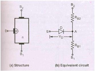
The  internal  resistances  of  the  two  bases  are  represented  as  RB1  and  RB2  In  the actual  construction,  the  terminal  E  is  closer  to  B2  as  compared  to  B1.  Hence resistance RB1 is more than the resistance RB2. The p-n junction is represented by a normal diode with VD as the drop across it. When the emitter diode is not conducting     then the resistance between the two bases B1 and B2 is called interbase resistance   denoted as RBB.

Its value ranges between 4k and 12K.

Intrinsic Stand off Ratio:

Consider UJT as shown in the to which supply VBB is connected with IE=0  i.e. emitter diode is not conducting,

Then the voltage drop across RB1 can be obtained by using potential divider rule.


The typical range of   is from 0.5 to 0.8. The voltage VRB1 is called intrinsic stand off voltage  because  it  keeps  the  emitter  diode  reversed  biased  for  all  the  emitter voltages less than VRB1

PRINCIPLE OF OPERATION:

While operating an UJT, the supply VBB is applied between B1 and B2 whilethe   variable   emitter   voltage   VE   is   applied   across   the   emitter   terminals.   This arrangement is shown in the Fig


Let us see the effect of change in VE. The potential of A is decided by   and is equal to  VBB.

Case1: VE

As  long  as  VE  is  less  than  VA,  the  p-n  junction  is  reverse  biased.  Hence  emitter current IE will not flow. Thus UJT is said to be OFF.

Case 2 : VE> Vp

The diode drop VD is generally between 0.3 to 0.7 V. Hence we can write,

Vp = VA+VD=  VBB+ VD

When  V  becomes  equal  to  or  greater  than  Vp  the  p-n  junction  becomes  forward biased and current IE flows. The UJT is said to be ON.

UJT CHARACTERISTICS


The  graph  of  emitter  current  against  emitter  voltage  plotted  for a  particularvalue  of  VBB  is  called  the  characteristics  of  UJT.  For  a  particular  fixed  value  of  VBB such characteristics is shown in the Fig.


The characteristics can be divided into three main regions which are,

1. Cut off region:  The  emitter  voltage  VE  is  less than  Vp  and  the  p-n  junction  is reverse  biased.  A  small  amount  of  reverse  saturation  current  flows  through  the device,  which  is  negligibly  small  of  the  order of  µA.  This  condition  remains  till  the peak point.

2. Negative resistance region: When the emitter voltage VE becomes equal to Vp the  p-n  junction  becomes  forward  biased  and  IE  starts  flowing.  The  voltage  across the device decreases in this region, though the current through the device increases.   Hence the region is called negative resistance region. This decreases time resistance RB1.  This  region  is  stable  and  used  in  many  applications.  This region  continues  fill valley point.

3. Saturation region: Increase in IE further valley point current IV drives the device
in  the  saturation  region.  The  voltage  corresponding  to  valley  point  is  called  valley point voltage denoted as Vv. In this region, further decrease in voltage does not take   place.  The  characteristic  is  similar  to  that  of  a semiconductor  diode,  in  this  region. The  active  region  i.e.  negative  resistance  regions,  the  holes  which  are  large  in number on p-side, get injected into n-side. This causes increase in free electrons in the n-type slab. This increases the conductivity i.e. decreases the resistivity. Hence the  resistance  R  decreases  in  this  region.  As  the  VBB  increases,  the  potential  VP corresponding to peak point will increase.

Applications

  • The UJT is mainly used in the triggering of other devices such as SCR.

  • It is also used in the sawtooth wave generators and some timing circuits.

  • The  most  popular  application  of  UJT  is  as  a  relaxation  oscillator  to  obtain short pulses for triggering of SCRs.

No comments:

Post a Comment

Labels

PROJECTS 8086 PIN CONFIGURATION 80X86 PROCESSORS TRANSDUCERS 8086 – ARCHITECTURE Hall-Effect Transducers INTEL 8085 OPTICAL MATERIALS BIPOLAR TRANSISTORS INTEL 8255 Optoelectronic Devices Thermistors thevenin's theorem MAXIMUM MODE CONFIGURATION OF 8086 SYSTEM ASSEMBLY LANGUAGE PROGRAMME OF 80X86 PROCESSORS POWER PLANT ENGINEERING PRIME MOVERS 8279 with 8085 MINIMUM MODE CONFIGURATION OF 8086 SYSTEM MISCELLANEOUS DEVICES MODERN ENGINEERING MATERIALS 8085 Processor- Q and A-1 BASIC CONCEPTS OF FLUID MECHANICS OSCILLATORS 8085 Processor- Q and A-2 Features of 8086 PUMPS AND TURBINES 8031/8051 MICROCONTROLLER Chemfet Transducers DIODES FIRST LAW OF THERMODYNAMICS METHOD OF STATEMENTS 8279 with 8086 HIGH VOLTAGE ENGINEERING OVERVOLATGES AND INSULATION COORDINATION Thermocouples 8251A to 8086 ARCHITECTURE OF 8031/8051 Angle-Beam Transducers DATA TRANSFER INSTRUCTIONS IN 8051/8031 INSTRUCTION SET FOR 8051/8031 INTEL 8279 KEYBOARD AND DISPLAY INTERFACES USING 8279 LOGICAL INSTRUCTIONS FOR 8051/8031 Photonic Transducers TECHNOLOGICAL TIPS THREE POINT STARTER 8257 with 8085 ARITHMETIC INSTRUCTIONS IN 8051/8031 LIGHTNING PHENOMENA Photoelectric Detectors Physical Strain Gage Transducers 8259 PROCESSOR APPLICATIONS OF HALL EFFECT BRANCHING INSTRUCTIONS FOR 8051/8031 CPU OF 8031/8051 Capacitive Transducers DECODER Electromagnetic Transducer Hall voltage INTEL 8051 MICROCONTROLLER INTEL 8251A Insulation Resistance Test PINS AND SIGNALS OF 8031/8051 Physical Transducers Resistive Transducer STARTERS Thermocouple Vacuum Gages USART-INTEL 8251A APPLICATIONs OF 8085 MICROPROCESSOR CAPACITANCE Data Transfer Instructions In 8086 Processors EARTH FAULT RELAY ELECTRIC MOTORS ELECTRICAL AND ELECTRONIC INSTRUMENTS ELECTRICAL BREAKDOWN IN GASES FIELD EFFECT TRANSISTOR (FET) INTEL 8257 IONIZATION AND DECAY PROCESSES Inductive Transducers Microprocessor and Microcontroller OVER CURRENT RELAY OVER CURRENT RELAY TESTING METHODS PhotoConductive Detectors PhotoVoltaic Detectors Registers Of 8051/8031 Microcontroller Testing Methods ADC INTERFACE AMPLIFIERS APPLICATIONS OF 8259 EARTH ELECTRODE RESISTANCE MEASUREMENT TESTING METHODS EARTH FAULT RELAY TESTING METHODS Electricity Ferrodynamic Wattmeter Fiber-Optic Transducers IC TESTER IC TESTER part-2 INTERRUPTS Intravascular imaging transducer LIGHTNING ARRESTERS MEASUREMENT SYSTEM Mechanical imaging transducers Mesh Current-2 Millman's Theorem NEGATIVE FEEDBACK Norton's Polarity Test Potentiometric transducers Ratio Test SERIAL DATA COMMUNICATION SFR OF 8051/8031 SOLIDS AND LIQUIDS Speed Control System 8085 Stepper Motor Control System Winding Resistance Test 20 MVA 6-digits 6-digits 7-segment LEDs 7-segment A-to-D A/D ADC ADVANTAGES OF CORONA ALTERNATOR BY POTIER & ASA METHOD ANALOG TO DIGITAL CONVERTER AUXILIARY TRANSFORMER AUXILIARY TRANSFORMER TESTING AUXILIARY TRANSFORMER TESTING METHODS Analog Devices A–D BERNOULLI’S PRINCIPLE BUS BAR BUS BAR TESTING Basic measuring circuits Bernoulli's Equation Bit Manipulation Instruction Buchholz relay test CORONA POWER LOSS CURRENT TRANSFORMER CURRENT TRANSFORMER TESTING Contact resistance test Current to voltage converter DAC INTERFACE DESCRIBE MULTIPLY-EXCITED Digital Storage Oscilloscope Display Driver Circuit E PROMER ELPLUS NT-111 EPROM AND STATIC RAM EXCITED MAGNETIC FIELD Electrical Machines II- Exp NO.1 Energy Meters FACTORS AFFECTING CORONA FLIP FLOPS Fluid Dynamics and Bernoulli's Equation Fluorescence Chemical Transducers Foil Strain Gages HALL EFFECT HIGH VOLTAGE ENGG HV test HYSTERESIS MOTOR Hall co-efficient Hall voltage and Hall Co-efficient High Voltage Insulator Coating Hot-wire anemometer How to Read a Capacitor? IC TESTER part-1 INSTRUMENT TRANSFORMERS Importance of Hall Effect Insulation resistance check Insulator Coating Knee point Test LEDs LEDs Display Driver LEDs Display Driver Circuit LM35 LOGIC CONTROLLER LPT LPT PORT LPT PORT EXPANDER LPT PORT LPT PORT EXTENDER Life Gone? MAGNETIC FIELD MAGNETIC FIELD SYSTEMS METHOD OF STATEMENT FOR TRANSFORMER STABILITY TEST METHODS OF REDUCING CORONA EFFECT MULTIPLY-EXCITED MULTIPLY-EXCITED MAGNETIC FIELD SYSTEMS Mesh Current Mesh Current-1 Moving Iron Instruments Multiplexing Network Theorems Node Voltage Method On-No Load And On Load Condition PLC PORT EXTENDER POTIER & ASA METHOD POWER TRANSFORMER POWER TRANSFORMER TESTING POWER TRANSFORMER TESTING METHODS PROGRAMMABLE LOGIC PROGRAMMABLE LOGIC CONTROLLER Parallel Port EXPANDER Paschen's law Piezoelectric Wave-Propagation Transducers Potential Transformer RADIO INTERFERENCE RECTIFIERS REGULATION OF ALTERNATOR REGULATION OF THREE PHASE ALTERNATOR Read a Capacitor SINGLY-EXCITED SOLIDS AND LIQUIDS Classical gas laws Secondary effects Semiconductor strain gages Speaker Driver Strain Gages Streamer theory Superposition Superposition theorem Swinburne’s Test TMOD TRANSFORMER TESTING METHODS Tape Recorder Three-Phase Wattmeter Transformer Tap Changer Transformer Testing Vector group test Virus Activity Voltage Insulator Coating Voltage To Frequency Converter Voltage to current converter What is analog-to-digital conversion Windows work for Nokia capacitor labels excitation current test magnetic balance voltage to frequency converter wiki electronic frequency converter testing voltage with a multimeter 50 hz voltages voltmeter

Search More Posts

Followers