An engine is a device that converts thermal energy into mechanical work. The thermal energy is produced by the combustion of air fuel mixture inside the cylinder by means of a spark produced by the spark plug. Since it uses thermal energy it is called as thermal engines. It is a source of power for many applications.
Cylinder:
v It is the part of the engine in which the conversion of thermal energy to
v mechanical work takes place. The piston reciprocates inside the cylinder.
v Since energy conversion takes place inside the cylinder it must withstand high pressure and temperature.
v It must be able to resist wear and tear and must dissipate heat. So material selection is an import ant consideration. Ordinary cast iron is used in light duty engines but in heavy duty engines alloy steels are used.
v The cylinders are provided with liners so that they can be replaced when worn out. Liners are made of nickel chrome iron.
Cylinder head:
v The cylinder head closes one side of the cylinder. They are usually cast as a single piece and are bolted to the top of the cylinder.
v Between the cylinder and the cylinder head, gasket is provided Gasket is provided in order to act as sealing (to prevent gases escaping during the expansion stroke) and also to reduce shock.
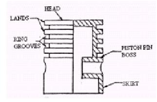
Piston and piston rings:
v Piston is the main part of the engine. The main function of the piston is to compress the charge and to transmit the gas force to the connecting rod during the power stroke.
v Piston rings are circumferential rings that are provided in the piston grooves.
v The piston rings are not fully circular; there is a clearance (Ring gap) between the two
v ends.
v This is provided because during the expansion stroke piston rings expand.
There are two types of piston rings
v Compression rings
v Oil scraper rings

Figure 1
v The upper rings are the compression rings.
v They help in sealing and preventing the gas from leaking past the piston into the casing.
v The lower rings are the oil scraper rings.
v They are provided to remove the oil film from the cylinder walls
Connecting rod:
v The connecting rod connects the piston and the crankshaft.
v The piston is connected to the connecting rod by means of gudgeon pin.
v It converts the reciprocating motion into rotary motion.
v The upper end of the connecting rod is called small head that is connected to the piston and the lower end is called big end.

Figure 2
Crankshaft:
v It is steel forged and smooth finished. Both the ends of the crankshaft are supported in the bearings.
v One end is provided with the flywheel. The crankshaft is provided with counter weights for balancing.

Figure 3
Cam and camshaft:
v The main function of the camshaft is to open and close the valves at the appropriate time.
The cam is operated by means of gear arrangement driven by the flywheel.
The cam is operated by means of gear arrangement driven by the flywheel.
v The cam converts rotary motion into linear motion that operates the rocker arm. The motion of the rocker arm operates the valves.
v Sometimes two camshafts are provided to operate inlet valve and exhaust valve
separately.

Valves:
v Valves play a major role in allowing the air fuel mixture into the cylinder (inlet valve) for combustion and also releasing the exhaust gases from the cylinder after combustion (outlet valve).

Manifolds:
v There are two types of manifolds
Inlet manifold:
v It is a pipe like structure that connects the carburetor with the inlet
valves. The air fuel mixture from the carburettor passes through the inlet manifold to
the inlet valves.

Fig shows A typical six-cylinder manifold
Exhaust manifold:
v This pipe like structure connects the outlet valve to the atmosphere. The exhaust gas from the cylinder passes through the exhaust manifold into the atmosphere.
Valve And Port Timing Diagrams
Valve timing Diagram
- A valve timing diagram is a representation of the positions of the crank when the various operations as inlet valve opening, closing, exhaust valve opening and closing and also the beginning and end of various strokes
- . The valves cannot open and close abruptly; it requires a finite period of time for its operation so a time advance is given for proper functioning. The timing of the valves is controlled by cam settings.
Valve timing for 4 stroke petrol (Spark Ignition) engine:
- Now let us see the various position of the crank when the inlet and exhaust
valves during the various processes. Inlet valve opening: The valve timing is different for low speed and high speed.
- The inlet valve opens before the piston reaches the TDC during the exhaust stroke. This is to ensure that the fresh charge enters the cylinder as soon the piston as soon as the piston starts to move down.
- Actual valve timing diagram for actual valve timing diagram for lowhigh speed 4 stroke SI engine speed 4 stroke SI engine
Inlet valve closing:
- The closing of the inlet valve takes place during the start of compression stroke (i.e. when the piston move from BDC to TDC after finishing suction stroke and the starting of compression stroke).
- I f the inlet valve is allowed to close exactly at BDC then less charge than the capacity enters during the suction stroke so the inlet valve closing is delayed to 20-25degrees after the crank reaches the BDC position during slow speed and 40-50degrees after the crank reaches the BDC position during high speed.
Exhaust valve opening:
- The exhaust valve opens at the end of expansion stroke. The exhaust valve opening is done before the piston reaches the BDC so as to provide more time for all the burnt gases to escape.
- The opening of the exhaust valve is necessary because if there are some burnt up gases left in the cylinder it may affect the cylinder walls and the spark plug. So the exhaust valve is opened 30-35degrees before BDC for slow speed and 45-50degrees before BDC for high speed.
Exhaust valve closing:
- The exhaust valve closing is also important to let out all the burnt gases. The time between the exhaust valve opening and the exhaust valve closing determines the amount of burnt gases that escapes.
- Usually the exhaust valve is closed 8-10after the piston reaches the TDC position. An important phenomenon in the valve timing diagram is the angle of overlap.
- The angle of overlap is the angle for which both the inlet valve and the exhaust valves remains opened. Thus it can be seen that from the diagram the
angle of overlap during slow speed is 5+8=13.
- The crank position at which ignition occurs is also indicated in the valve timing diagram. The ignition is provided 38-40before TDC during compression.
CYLINDER LINERS AND SLEEVES, BUSHING, ENGINE BEARINGS, Engine Valves and Guides, PISTON PIN AND RING.
ReplyDeleteThe post is written in very a good manner and it contains many useful information for me. homepage
ReplyDelete