Induction generator
The bottom part of the circle diagram covers generator mode of induction machines at threephase supply. Over-synchronous speed (s >0)is to be achieved by accordant driving in order to work as generator. The reversal of the energy flow direction is regarded in the ecd with appliance of (R2/S)<0 and therefore a reversal from sink towards source.

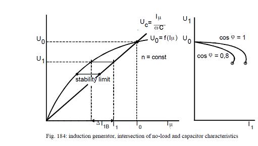
The stator current reactive component direction remains the same at changeover from motor to generator mode. Thus induction machines are not able to autonomously excite required magnetizing current, but need to be supplied by external sources. Since synchronous generators are able to provide lagging reactive power, mains operation appears trouble-free. If induction machines are supposed to operate in solitary operation without mains connection (e.g. auxiliary power supplies, alternator in automotive applications, etc.), capacitor banks need to be connected in parallel for coverage of required reactive power. Besides described application samples, maintenance-free induction machines in solitary operation are utilized for run-of-river power stations as well as for wind-energy generators. Similar to DC machines, self excitation is possible for inductions machines in solitary operation as well. Saturation dependent machine reactance and external capacitors form a resonating circuit, which is excited to oscillate by current peak or remanence magnetism for actuated rotors. A stable operating point ensues for U0= UCat the intersection of no-load characteristic and capacitor Characteristic.
The amount of no-load voltage can be adjusted by the choice of the utilized capacitor value. The no-load characteristic U =f( I U ) applies for constant speed without load =>0 wirk I =, whereas the capacitor characteristic UC= I U / ωC complies with the reactive voltage drop along the capacitor, to be connected in parallel.
If the machine is loaded with active current I1, the required reactive current amount increased about ^I1B . Since the capacitor is not able to provide more reactive current in real, voltage drops until U1. Therefore the machine load can be increased until the stability limit is reached, which means, an additional reactive current demand can not be covered. The according load characteristics U 1 =f( I1 take after those of entirely excited DC shunt generators
The bottom part of the circle diagram covers generator mode of induction machines at threephase supply. Over-synchronous speed (s >0)is to be achieved by accordant driving in order to work as generator. The reversal of the energy flow direction is regarded in the ecd with appliance of (R2/S)<0 and therefore a reversal from sink towards source.
The stator current reactive component direction remains the same at changeover from motor to generator mode. Thus induction machines are not able to autonomously excite required magnetizing current, but need to be supplied by external sources. Since synchronous generators are able to provide lagging reactive power, mains operation appears trouble-free. If induction machines are supposed to operate in solitary operation without mains connection (e.g. auxiliary power supplies, alternator in automotive applications, etc.), capacitor banks need to be connected in parallel for coverage of required reactive power. Besides described application samples, maintenance-free induction machines in solitary operation are utilized for run-of-river power stations as well as for wind-energy generators. Similar to DC machines, self excitation is possible for inductions machines in solitary operation as well. Saturation dependent machine reactance and external capacitors form a resonating circuit, which is excited to oscillate by current peak or remanence magnetism for actuated rotors. A stable operating point ensues for U0= UCat the intersection of no-load characteristic and capacitor Characteristic.
The amount of no-load voltage can be adjusted by the choice of the utilized capacitor value. The no-load characteristic U =f( I U ) applies for constant speed without load =>0 wirk I =, whereas the capacitor characteristic UC= I U / ωC complies with the reactive voltage drop along the capacitor, to be connected in parallel.
If the machine is loaded with active current I1, the required reactive current amount increased about ^I1B . Since the capacitor is not able to provide more reactive current in real, voltage drops until U1. Therefore the machine load can be increased until the stability limit is reached, which means, an additional reactive current demand can not be covered. The according load characteristics U 1 =f( I1 take after those of entirely excited DC shunt generators
No comments:
Post a Comment