Trio / Kenwood TS-430S information.

 Service manual is available from GM1SXX and LA2QAA. Service manual is available from GM1SXX and LA2QAA.
Common faults:
Intermittent Drop in Power Output, Erratic ALC behaviour, SSB distortion:
Unless your TS430 has been in a store room since it was manufactured, you have an appointment with the vias (PCB through-hole connections) and soldered joints around the PA final transistors. All units will eventually fail through solder-fatigue; brought on by constant temperature cycling, and exacerbated by embrittlement due to migration of gold atoms from the transistor tabs. This is not a problem exclusive to the TS430, but the cheap construction, particularly the SRBP circuit board with riveted vias, is something of a liability in this case. This is one area in which periodic maintenance can help to prevent disaster; the disaster in question being the open-circuiting of the PA transistor base connections, and consequent failure of the driver and driver-bias transistors. Warning signs are (as in the heading) one or more of the following: Intermittent variation in output power, erratic ALC level indication, and reports of audio distortion on SSB signals.
If you are receiving reports of distorted SSB, one simple way to isolate the problem is to listen to the output of the SSB exciter. To do this you will need an additional short-wave receiver capable of working with headphones, and a dummy load for listening to the final output. Simply pull the final drive cable from the RF board and insert a short length of hook-up wire (~0.5m) into the socket, taking care not to short the drive output to ground. A clean signal from the exciter indicates that the problem is definitely with the PA.
The final unit must be removed from the transceiver and the PCB detached from the heat-sink to gain access to the offending connections. This may seem daunting, but is actually straightforward if a few sensible precautions are taken during the dismantling and recommissioning phases. A suitable procedure is as follows:
1) Having removed the transceiver top and bottom covers, unscrew and pull out the back panel with the final (PA) unit attached to it. Unplug the antenna connector from the LPF board. Unplug the final drive (co-ax) cable from the RF board. Unplug the final RF output cable and the fan and thermistor connectors from the LPF board. Fold the back-panel down as far as possible and remove the internal cover from the final amp. The remaining wires can now be unplugged, except for the +13.8V (thick red wire) supplying the output transistors, which should be unsoldered from the tag next to the power input connector. Unscrew the final amp module from the rear panel and remove it. Some of the wires leading to the rear-panel connectors are quite likely to fall-off during reassembly, so make a note of the colours now.
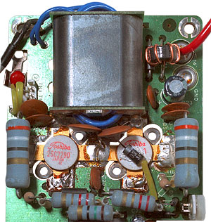
2) Remove the final amp PCB retaining screws, transistor retaining screws, and the thermistor retaining screw, and separate the board from the heat-sink. Note which transistors require mica washers, then clean off all of the old heat-sink compound with isopropanol and cotton buds. Inspect the PA transistor base via rivet heads (2 per transistor) on the underside of the PCB. A dark circle in the solder indicates that the connection has failed (even though it may exhibit a low DC resistance at the time of examination). The problem is clearly evident in the photograph below (yellow arrows), and the module shown was indeed producing distorted SSB. A cursory examination of the board also reveals failure of the emitter vias, but since the emitters are connected to the ground plane on both sides of the board, these additional failures do not prevent the unit from working. |

| Bridge the PA base vias with wire. This can be done without removing the transistors, by passing a wire through the gap to the side of the transistor tab. Also inspect all of the other vias on the board, particularly those at the driver transistors, and resolder as necessary. |

| Heatsink in preparation for reassembly, showing which transistors require mica washers. |
Points to note during reassembly and testing:
 Avoid using excess heat-sink compound. Avoid using excess heat-sink compound.
Do not over tighten transistor retaining screws. Leave time for the grease to extrude and then retighten.
Re-solder SOE transistors after reassembly to relieve stresses.
Remove old solder as far as possible and replace it, to reduce gold contamination.
Check for shorts - bases measure 7.5Ω to ground. Collectors o/c fwd, 0.53V rev.
Re-commission using a current-limiting PSU.
Test initially at low power levels in case of loose or shorted output connectors. The operation of the SWR protection circuit depends on a proper connection between it and the amplifier.
Reset Bias according to the procedure in the service manual.
Check that the antenna connector is not loose. A faulty ground connection at this point can cause a bad SWR and activate the protection circuitry. | 
Output transformer and output transistors |

| Relay-switched Low-pass filters used to remove harmonics from the transmitter output. |
TS430s Transmitter Coverage Modifications:
Few people will have legitimate reasons to transmit outside of the Amateur bands, but there is nevertheless considerable interest in the fact that some synthesised transceivers can be modified easily to do so. Consequently, there are various articles published on the internet which give general coverage transmission modifications for the TS-430S; and in keeping with the provenance of the information, most describe botches of varying horribleness. In particular, there is no need to crush or cut any diodes or resistors; and some of the suggested mods unwittingly remove the TX inhibit signals for frequencies below 1.6MHz, in which range the transmitter will either radiate strong spurious signals or self-destruct.
The main legal restriction signals from the control unit are grouped on connector 10 on the RF board. The connector carries three logic signals: TXI, WRC, and PD, their descriptions being as follows:
| TXI | TX Inhibit - out of amateur band. |
| WRC | TX Inhibit - out of WARC band |
| PD | Power down (ie, reduction) on 28MHz (for USA) |
The behaviour of these lines may vary depending on the serial number and country of purchase.
Additional transmitter inhibit signals are derived from the receiver roofing-filter selection logic, on the RF board itself; these being used to prevent transmission in the range 0.15 to 1.6MHz, and to apply additional restrictions in regions where not all WARC bands are allocated. For M-type transceivers, regional WARC band restrictions can be removed by unplugging the white link-wire on the RF board (see the user manual, p22). Other versions do not have the WARC band restriction components fitted, and so transmit on all amateur bands without modification. When configured for full amateur use, the transmitter frequency coverage is as follows:
1.6 - 2, 3 - 4, 6.9 - 7.5, 10 - 10.5, 13.9 - 15, 18 - 19, 20.9 - 22, 24 - 25, 27.9 - 30 MHz.
Note that that these ranges already give considerable coverage outside of the amateur bands, and place the onus on the operator to avoid unallocated frequencies. If you require additional coverage, removing the plug from connector 10 enables transmission at full power over the complete HF range from 1.6 to 30MHz.
The author has, for some time, used a TS430S (with connector 10 of the RF module unplugged) as a high-power 1.6 - 30MHz signal generator for the testing of transmission line bridges, current transformers, and matching networks. The only problem experienced is that the output at around 8.3MHz is unusable due to a strong spurious signal from the IF amplifier. This, of course, is all dummy-load work. A good look at the output with a spectrum analyser is recommended before using it on the air.
Note that it is not necessary to remove plug 10 when using the transverter socket, since the transverter output is not affected by the legal restriction signals.
 Unused Digit of the Frequency Readout: Unused Digit of the Frequency Readout:
The user manual describes a modification which can be carried out to give 10Hz readout.  Do not do this mod! The last digit is blanked because it reads nonsense. The author found it necessary to reverse this mod. because it introduced statistical bias in accurate frequency measurements. Do not do this mod! The last digit is blanked because it reads nonsense. The author found it necessary to reverse this mod. because it introduced statistical bias in accurate frequency measurements.
Resetting the Microcontroller:
Set the function switch to 'A'
Switch power on while holding the A=B key. Then release the A=B key.
(Source: TS-430S service manual, p46).
"TS430S IF Filter Mod", Robert A Witte KB0CY, Ham Radio, May 1984, p125.
Allows the narrow CW filter to be used in USB and LSB modes, for those who do not have the narrow SSB filter fitted.
DWK G3YNH. Last update 29th March 2007. Version 1.00 (Unicode) |
Equipment Reviews:
Trio TS430S, Peter Hart G3SJX, Rad Com, June 1985. pp441-444.
Trio TS930S and TS940S, Peter Hart G3SJX, Rad Com, May 1986, pp328-333.
Related Links:
Service manual is available from
GM1SXX and LA2QAA.
Mauritron Technical Services: UK source for service manuals..
Vine Antenna Products INRAD filters for Kenwood and other transceivers.
salut a tous je hh2opor
ReplyDeleteje viens de me procurer un ts-430s
alimente sur un ps-50 dc power supply
la frequence ne s'affiche pas
j'ai besoin votre aide