A. PREFACE
Surfing on the net to find something new is very exited. This time, I bump to Chrono-Art site made by Barry Gamble. He made many good view of unusual clock. One I really want to build now is like proto-time clock. This is a linear clock. Read out the times from the left to the right position. From bottom to top. I plan to use PIC microcontroller also like the other of my clock design (PIC16F628/A). May be the option not to much like his design, but its really very inspired. While I have a few days spare time on these National day Idul Fitri 2009, a week vacation days. So the project begin!!!

B. SCHEMATIC
By modifying VSC clock design, I draw another circuit to drive this linear clock. The controller still use PIC16F628/A type. Original display indicator use 36 pieces led. I change it like these : 12 pieces for hours indicator, 5 pieces for ten of minutes, 9 pieces for minutes unit, and 6 pieces for seconds display in binary counting. Total active display are 32 pieces led. To accommodate these option, I use 4 x 8 I/O with multiplexed output, 4 port-A and 8 port-B. As always input RA-4 for power failure input, and RA-5 input for setting the time (this option only available for PIC16F628A). In fact that I still need 2 indicators for AM/PM sign. May be this option could be steal from any other input, since all the I/O already used. I hope so, I will cover this option in the firmware section later. No need for leds direction indicator since it is a linear clock. Over all schematic are like below. After a few times changed, at last the design completed. Here it is :
C. LAYOUT
By make some changes to the VSC clock PCB design, the prototype done. Not to much different for the controller. This part is for microcontroller only. Led display indicator put in another piece. Some connections are made directly from flying wire connections. The colors just to make the different view only. The real color matched by led colors that could be found on the market. Note that, my prototype a little different from here, because I made the earlier version. This is the final version.


Here is the PCB layout (Linear_ClockP.pcb, Linear_Clock_Layout.pdf, Linear_Clock_Artwork.pdf).
D. PART LIST
Here are the part list for this Linear Clock circuit :
   1. Resistors :
      R1 ~ R4, R5 = 220 Ohm, 1/4W, 5% ............................ 5 pcs
      R6, R7 = 10k, 1/4W, 5% ..................................... 2 pcs
      R8, R10, R11 = 4k7, 1/4W, 5% ............................... 3 pcs
      R9 = 100 Ohm, 1/4W, 5% ..................................... 1 pcs
2. Capasitors : C1 ~ C2 = 22 pF (for oscillator) ........................... 2 pcs C3 = 100 nF (for IC decoupling, used as necessary).......... 1 pcs C4 = 33 uF/16 V ............................................ 1 pcs C5 = 100 uF/ 16 V .......................................... 1 pcs
   3. Semiconductors :
      IC1  = PIC16F628/A (PIC microcontroller) ................... 1 pcs
      D1 = 1N914 (Silicon diode) ................................. 1 pcs
      D2, BD = 1N4007 (Silicon diode) ............................ 5 pcs
      DZ = 5V1 (Zener diode) ..................................... 1 pcs
      LED1 ~ LED12 = 5mm, Red (Clear type) (for hours ind) ...... 12 pcs
      LED13 ~ LED17 = 5mm, Grn (Clear type) (for minutes-ten ind). 5 pcs
      LED18 ~ LED26 = 5mm, Blu (Clear type) (for minutes-unit ind) 9 pcs
      LED27 ~ LED32 = 5mm, Orange (Clear type) (for seconds ind) . 6 pcs
      LED33, LED34 = 5mm, Whi (Clear type) (for delimiter ind) ... 2 pcs
      LED35 = 5mm, light-Blu (Clear type) (for PM ind) ........... 1 pcs
      LED36 = 5mm, Yel (Clear type) (for AM ind) ................. 1 pcs
   4. Others :
      X1 = 4 MHz (Clock Crystal oscillator) ...................... 1 pcs
      Optional IC socket for 18-pins (use 20-pins) ............... 1 pcs
      Optional terminal connector CON1 ~ CON2 = 2 pin (power) .... 2 pcs
      Optional terminal connector CON3 = 5 pin (sip) ............. 2 pcs
      Optional terminal connector CON4 = 8 pin (dip) ............. 2 pcs
      S1 = Miniature push button (Push on) ....................... 1 pcs
      PCB = 4 x 6 cm, 16 x 6 cm (single layer) ................... 2 pcs
      T1 = Miniature transformer P=220V/S=6V3, 100mA, 1W ......... 1 pcs
E. FIRMWARE
The firmware follow VSC Clock algorithm, except that this time it must be inverted. Displayed visual indicators steady-on for all leds, but the time showed by the blank leds. All leds are multiplexed. So there are about 34 leds must be multiplexed. As already mention before, for this PIC type, I programmed it with my_rcd_programmer, I got it from RCD programmer site. Using a free software from DL4YHF's WinPic - A PIC Programmer for Windows, the chip could be programmed well. The firmware write in ASM type, compiled with the free MPLAB assembler compiler also.
Some changes must be made. First, by using the 1024 usec. interrupts, the refresh rate display leds is too low (about 28 times per second).This may seen some flicker to the leds display. So the interrupts changed to 512 usec. double the refresh rate to be come about 50 times per seconds. This is more rational as the power line also use it too. Second, Normal display usual show the time by the glowing leds. But for this linear clock, it's better to off the proper time number, and show another leds steady. So, we can read it easily by counting another glowing leds. But for the study, I will put it here also, both of it! Third, and this is the most difficult part, I have run out all the I/O and nothing left to AM/PM option leds. In the begining, I think that I could use the technique to run the leds like VSC clock before, but the sequential scanning make it steady on for all of the time. Then I search the net, and found the new technique (Charlie plexing) to run the leds, but because the layout a little different, it can't be used here. May be I will used it for the next project, Sun Clock project! Then I go back to the earlier project PIC Digital Clock, and found the solution! Stealing the I/O function technique. Power failure input steady on if the power is on, then by making it low for a momentarily (when the checking already done, then the leds could be make on for a little time (in another words, make it on and off for about 50 times). What a solution!!!
With the same algorithm as before, the time clock not perfectly accurate, because the overload of display routine (instruction latency time). I already tried to optimize that, but not successful yet. For normal display it maybe not effected at all, but for inverting display, it took a lot. With my experiment when the clock run in silent mode (battery back-up), nothing to display, the time is still accurate, but when it run normally for a night, it's about 2 to 3 minutes late. Must put some correction later in the routine.
After I modified many times, then at last the time about perfect. The routine back to 1024 usec. timer interrupt handler again. Because this is the very steady and not make to much noise to all routine. The routine separate by 2 parts, ie: one part for count up the time using interrupt handler timer 1024 usec. and the other is the clock body routine. Maybe it needs a little touch, since the time may go faster by time to time.
At last, the project complete. Since I had a few days spare during the new year 2010. After a few trial error, the routine about perfect, only a few second bias for a day. But I was a little confused in my experiment, I wonder when I programmed more then one PIC, every PIC gave the different result in running. So for you who want a perfect result must try to programmed the PIC with different value for adjusting the time (see the line in my routine under the tag "empirically test value"). Try to adjust this value until you get the very small deviate of the clock. To fill my curiosity, I tried 2 kind of routine for this clock, ie: interrupt handler timer using 1024usec and interrupt handler timer using 512 usec. Which one is the best? You choose by your self!!! I prefer the 512 usec routine, because it gave the almost perfect time!
Here is the firmware, Linear_Clock4 for 512 usec interrupt and Linear_Clock5 for 1024 usec interrupt :
Linear_Clock (Linear_Clock4.asm, Linear_Clock4.hex, Linear_Clock4_Inv.asm, Linear_Clock4_Inv.hex; Linear_Clock5.asm, Linear_Clock5.hex, Linear_Clock5_Inv.asm, Linear_Clock5_Inv.hex).
After running the linear clock about 6 months, then the clock seems to be disordered. I don't have many time since then and I lost my curiosity too, then the clock be ignored until now. I have a little spare time now and I will make some improvement to the firmware, because the firmware seems to much deviated from the real time clocking. This time I implemented the one sec. bresenham algorithm to the routine. I hope that it could be run better!!! The routine still the same to the old one, but the interrupt timer changed to 256 msec. timer (the smallest one) using the wdt timer selection. I still run the prototype to try!!!
Here is the revision firmware using new interrupt timer (Linear_Clock5_1.asm, Linear_Clock5_1.hex, Linear_Clock5_1_Inv.asm, Linear_Clock5_1_inv.hex).
F. PROTOTYPE
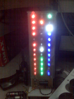
Here is my prototype clock looks like. The over all size about 25 x 5 x 4 cm. The board put on a piece of thin multiplex board, and cover using hard plastic packaging. A small transformer included on the board, so the size can be made very compact. The screen display may be add using a blur plastic transparent, so the spot will be block by it. Very good view from the front side.


H. IMPLEMENTATION
Here is some picture of my linear clock prototype and I plan to put it besides the other of my clock designs. Just to compare it and to view the difference between any designs. Just another cool clock design!!!


- Development phase view (video_1.3gp) - the linear clock running at noon (15 sec).
- Development phase view (video_2.3gp) - watch the change between seconds to minute count (10 sec).
I. HOW TO READ
Someone always ask, how to read the clock?See, the red leds at the left column represent hours count form 1 to 12, green leds at the center represent minutes ten unit count from 1(0) to 5(0), and blue leds at the right column represent the minutes unit count from 1 to 9, while the white leds is for delimiter only and to represent the position count for 6 and 10 locations, the orange leds at the top center represent seconds in binary format count but inverting it from 1 to 59, and the last two leds at the top right corner represent for AM or PM time. Counting number from bottom to top and the clock represent from left to right and top. eg: the above first picture represent the clock at 08:52:28 - PM.
No comments:
Post a Comment